Daylight Switch Wiring Diagram Pdf
3 Way Switched Outlet Wiring. Power up system 3.
 Diagram 280z Ignition Switch Wiring Diagram Full Version Hd Quality
Basics 14 AOV Schematic with Block included Basics 15 Wiring or Connection.

Daylight switch wiring diagram pdf. Describe and identify the diagram component U. HOW TO READ THE WIRING DIAGRAMS - Wire Colour Codes A-9 WIRE COLOUR CODES Wire colours are identified by the follow colour codes. Daylight Running Lights - Wiring Diagram Pin 1 Pin 13 The LED lights are fed from the caravan fridge circuit therefore only illuminating when the engine is running.
A diagram that represents the elements of a system using abstract graphic drawings or realistic pictures. Code Wire colour Code Wire colour B Black P Pink BR Brown R Red G Green SB Sky blue GR Gray SI Silver L Blue V Violet LG Light green W White O Orange Y Yellow If a cable has two colours the first of the two colour code. 1 Step-By-Step Guide Book on Home Wiring No.
Next page 3 4RUNNER 2 EC1 AM2 7 L- R 4 AM1 ACC IG1 IG2 ST2 2 3 E 15 2 W-B 5 3 1 2 E 2 1F 10 From STA Fuse NO. Technical information 3 Standard Diagrams Transfer between 2 sources - 1 Bus bar COMUT 041 A Load G S1 G S2 P1 P2 Standard solution COMUT 042 A Load S1 S2 Q1 Q2 ATS. Basics 8 AOV Elementary Block Diagram.
Fiber optic cable electrical connections boundary seal to be in accordance with article 501-5. Wiring diagram book a1 15 b1 b2 16 18 b3 a2 b1 b3 15 supply voltage 16 18 l m h 2 levels b2 l1 f u 1 460 v f u 2 l2 l3 gnd h1 h3 h2 h4 f u. 18-3 awg stranded wire shielded or nonshielded blue control-occ red 10-30 vdc load a blue neutral hot use black lead for 120 vac.
Follow circuit wiring information found on the inside of low voltage terminal door. Start fiber optic transceiver class 9005 type ft fiber optic push button selector switch limit switch etc. Basics 9 416 kV Pump Schematic.
The source is at the SW1 where the hot is connected to. Pdf dwg software Application F5 LL-EVO 2-Room 1 or 3-Zone 1-Daylight Zone. Connect live or a hot wire to the common or black terminal of the first switch.
Line voltage automatic dimming photocontrols line voltage onoff photocontrols low voltage onoff automatic. Describe the meaning of the G-W in diagram component R. Basics 10 480 V Pump Schematic.
Pdf dwg software Application F6 LL-EVO 2-Room 1 or 3-Zone 2-Daylight Zone. Daylight Harvesting Standard Sensor Product Line Selling Sensor Switch 2 3 4 6. Either Blue wire can be used for Hot or Circuit 2 2.
SENSOR SWITCH OVERVIEW The Sensor Switch product line of stand alone occupancy sensors and indooroutdoor daylight controllers are engineered to provide solutions for a. In the 0-10V product the grey wire. The products are designed to automatically activate lighting at sunset ensuring outside areas are.
Describe the meaning of the C13 in the diagram component Q. Motorised Switch CL NCL G Q1 Q2 ATS Automatic Transfer Switch Protection arent shown on the following schemes Summary. 2 Step-By-Step Guide Book on Home Plumbing and the No.
More neutral wires may be bundled in the back of the switch. 1 E03 A 16 1I 4 2 11 2 AB E 7 20 E 6D 5D 4D. Daylight Control Wiring Diagrams BLK - 120 V ORN - 277 V CAP OFF PP20 LOW VOLTAGE AUTOMATIC DIMMING PHOTOCONTROLS BLK - 120 V ORN - 277 V CAP OFF PP20 0-10 VDC BALLAST DZ - DUAL ZONE OPTION Wire to an additional 0-10 VDC Ballast.
678M16 wiring diagrampdf 7 September 2007 379301 Rev0 CN13722 Wiring Diagram for 678M16 Intermediate Switch Rear view of switches 2 Way Switch Intermediate Switch 2 Way Switch Any number of Intermediate Switches can be wired between the 2 Way Switches P N LOAD L3 L2 L1 L1 L4 L2 L3 L2 678M16 wiring diagrampdf 7 September 2007 379301 Rev0 CN13722. Application F4 LL-EVO 2-Room 2-Zone 2-Daylight Zone. Connect wires per WIRING DIAGRAM as follows.
Switches can be used to turn loads on or off. Maximum wire length from timer switch to all installed remotes cannot exceed 300 ft 90 m. 3 Step-By-Step Guide Book on Room Finishing can be found in various do-it-yourself stores throughout the United States.
Daylight control wiring diagrams blk - 120 v orn - 277 v cap off pp20 low voltage automatic dimming photocontrols blk - 120 v orn - 277 v cap off pp20 0-10 vdc ballast dz - dual zone option wire to an additional 0-10 vdc ballast. So that we attempted to uncover some terrific photocell switch wiring diagram. In this diagram two 3 way switches control a wall receptacle outlet that may be used to control a lamp from two entrances to a room.
The Clipsal Sunset Switch Series is a range of high quality weather protected photoelectric daylight sensors with adjustable time and lux facilities. Describe the meaning of the 2 in diagram component S. Neutral wire is for Room Controller b.
Timer Switch WIRING TIMER SWITCH. Use black and red wires to connect traveler or brass-colored terminals of the first switch and the second switch. A diagram that uses lines to represent the wires.
How To Install And Wire A Photocell Switch In A Lighting with regard to Photocell Switch Wiring Diagram image size 784 X 458 px and to view image details please click the image. Wiring Clear Connect RF Communication DZ 1 DZ 2 Daylight Zones Low-voltage DZ 1 DZ 1 DZ 1 wiring 2 2 2 2 2 2 2 2 2 1 1 1 DZ 2 DZ 2 DZ 2 1 2 Dimming sensing personal control and daylight harvesting j-box PowPak dimming module with 0 10 V control Junction-box mounted dimming module that controls 0 10 V fixtures. The timer switch must be installed in a wall box that has a Line Hot connection.
Connect power load and control wiring as shown on appropriate Kit Wiring Diagram a. Connect the white Neutral wire 2 from the switch box to the NEUTRAL terminal of the timer. UNDERSTANDING TOYOTA WIRING DIAGRAMS WORKSHEET 1 1.
Three-wire cable runs between the switches and the outlet. If daylight sensor is enabled and light level is above setpoint switchpack connected to yellow lead will not turn load on. Wire leads are color coded to match circuit labels.
Basics 7 416 kV 3-Line Diagram. The relay ensures when the vehicle lights are turned on the LED lights extinguish. Electrician Circuit Drawings and Wiring Diagrams Youth Explore Trades Skills 3 Pictorial diagram.
Home house repair do it yourself guide book room finishing plumbing wiring outlets switches power framing drywall doors paneling ceiling time toilets bathroom kitchen. This circuit is wired the same way as the 3 way lights at this link. Green or bare copper wire in wall box to timer switch Green lead.
Basics 11 MOV Schematic with Block included Basics 12 12-208 VAC Panel Diagram. Connect the Traveler-2 wire 7 to LINE terminal of the timer. Basics 13 Valve Limit Switch Legend.
Describe the meaning of the SD in diagram component T. Here is a schematics in PDF format and a step-by-step process of connecting the wires with power at the switch. M OVERALL ELECTRICAL WIRING DIAGRAM 1 2 34 W-L J 7 JUNCTION CONNECTOR D GR- B B-L 14 IG1 2 2 22 MREL B- R 2 1 See Engine Control System 2 E 4 IGSW Cont.
IgCC 2012 International Green Construction Code Automatic Daylight Controls 6095 Automatic daylight controls shall be provided for all daylight zones. Connect the Traveler-1 wire 5 to the TRAVELER terminal of the timer. The earths must be seperate within the caravan.
Multiple daylight zones must be separately controlled from the general area lighting and can be controlled either manually or via an automatic daylight sensor. Truly we have been realized that photocell switch wiring diagram is being one of the most popular topic at this time.

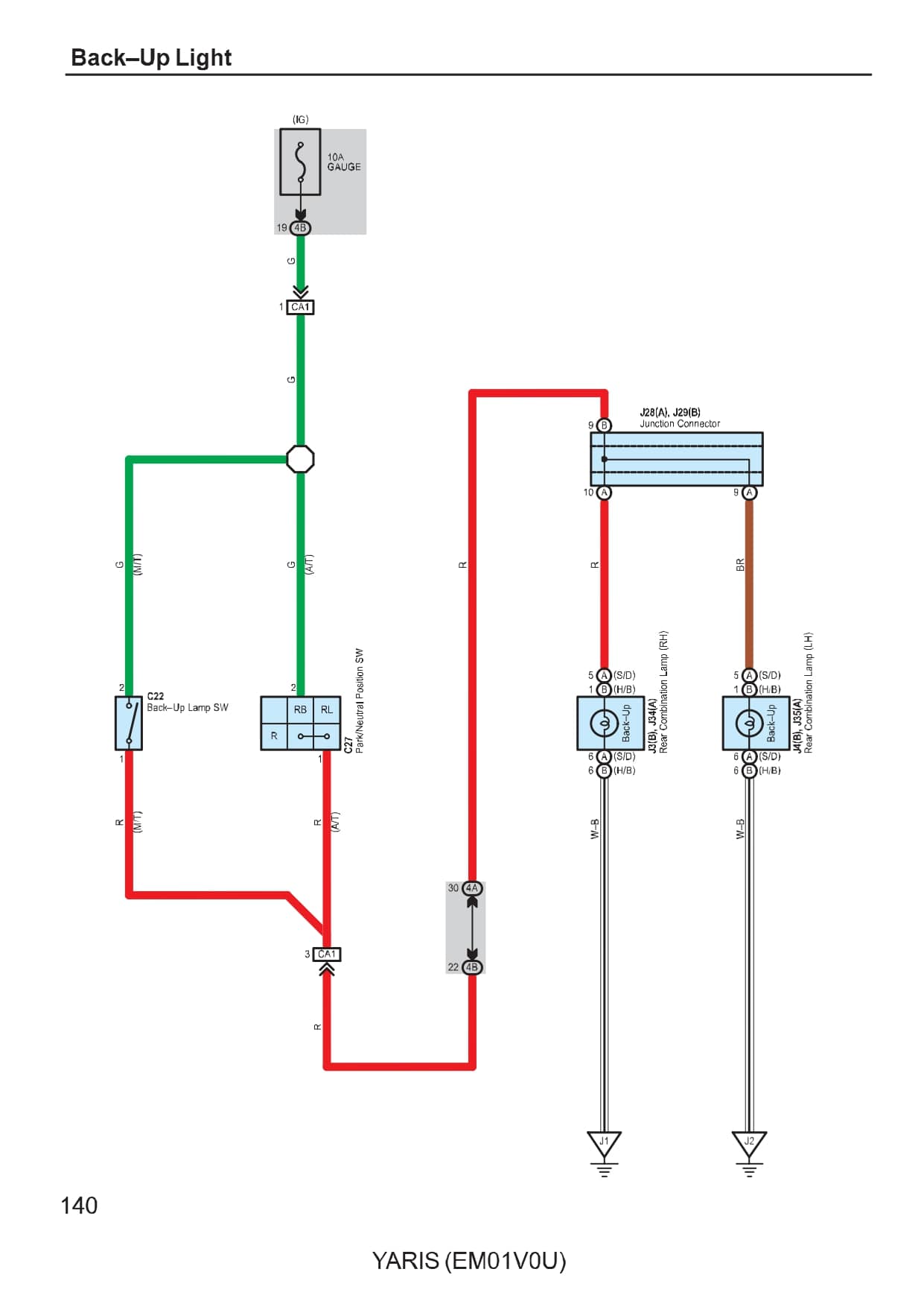 Diagram Toyota Yaris Wiring Diagram En Espaaƒae A A Ol Full Version Hd Quality
 Pin On Kick Ass Tech
 Click For A Larger View In 2021 Electrical Circuit Diagram Electrical Diagram Motorcycle Wiring
 2 Gang Switch Wiring Actual And Schematic Diagram Youtube Diagram Switch Outlet Wiring
 Pinterest

 Day Night Automatic Triac Switch Circuit Electronic Circuit Projects Electronic Circuit Design Electronic Schematics
 Diagram Universal Power Window Switch Wiring Diagram Full Version Hd Quality
 Diagram Light Switch Wiring Diagram New Zealand Full Version Hd Quality
Pin On Garage Tools
 36 Unexceeded Mental Picture Of Lighting Contactor Wiring Diagram In 2021 Diagram Electricity Wire
 Day Night Or Light Switching Connecting Youtube Light Sensor Night Connected Light

 Pin By Akadri Oluwasegun On Segun Circuit Diagram Ceiling Fan Circuit
 Hero Honda Glamour Engine Diagram Diagram Electrical Diagram Electrical Wiring Diagram
 Diagram Compressor Pressure Switch Wiring Diagram 120v Full Version Hd Quality
 Diagram Simple Gm Power Window Wiring Diagram Full Version Hd Quality
 Diagram 110 Wiring Diagram Two Ceiling Light Full Version Hd Quality
No comments for "Daylight Switch Wiring Diagram Pdf"
Post a Comment