Ct Shorting Terminal Block Wiring Diagram
What is the reason and explain with details. Cover All Flexitest Switch covers provide a tough insulated enclosure for the switch and are made from a durable plastic material.
 Ct Shorting Blocks In Stock For Quick Delivery
Safer installation or removal of meters from service.
Ct shorting terminal block wiring diagram. Any shorting winding effectively shorts the entire CT. To connect the CT lead wires to the CT input terminals first strip about 14 6 mm of insulation off the end of one of the wires twist the bare strands together insert the end into the terminal block and tighten the screw securely. If ring terminal is desired use U prefix rather than UC.
Physical Specifications562 Line to Line Spacing Wire Range 10-18 AWG Copper Crimp Ring Lug or Spade Lug Electrical Ratings. I had designed for shorting test switches between the CTs and the relay but was told that industry standard for the differential relay is not to install shorting test switches but wire the CT through terminal blocks to the relay instead. Covers are fastened to the switches with thumbnuts.
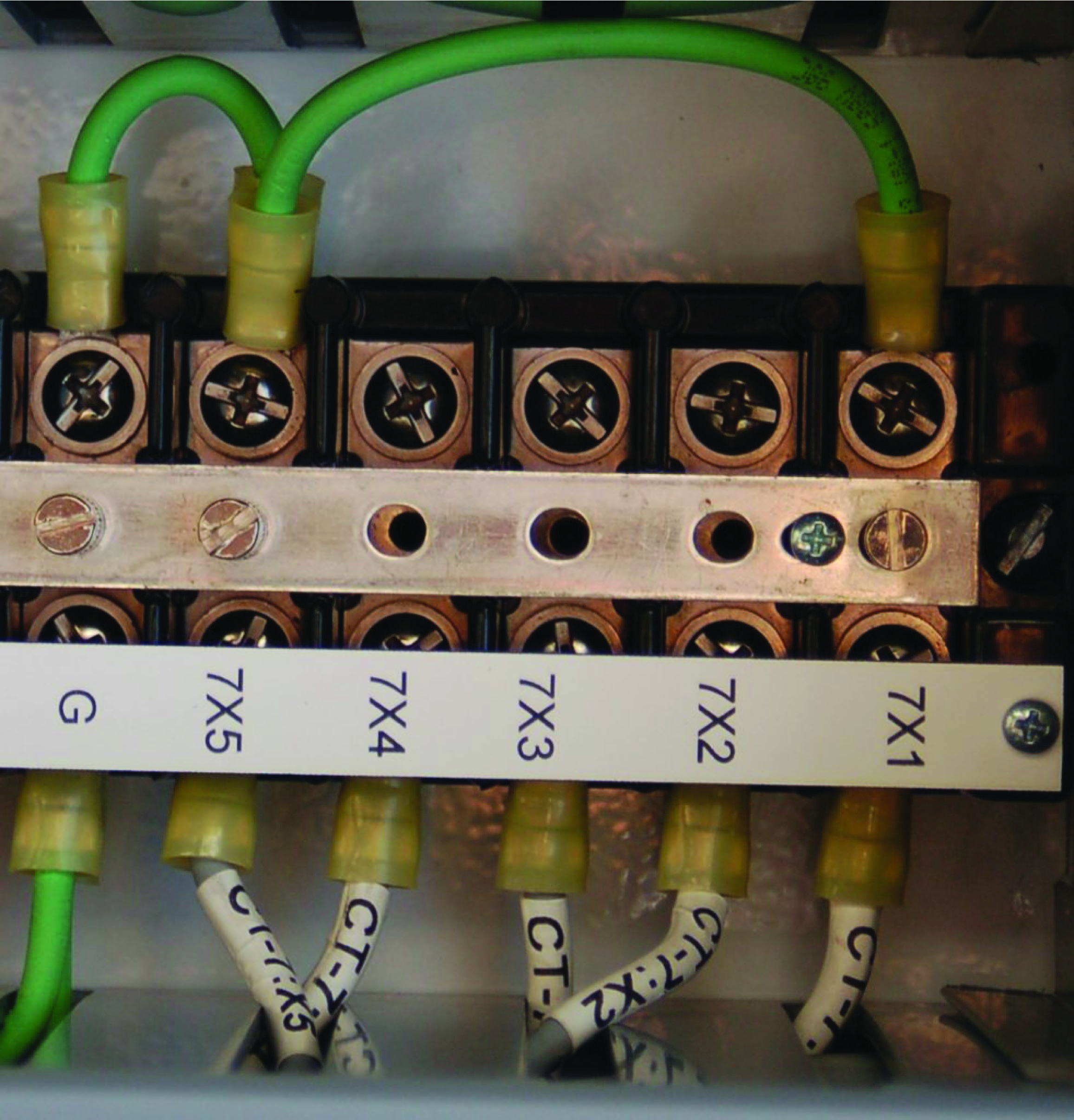
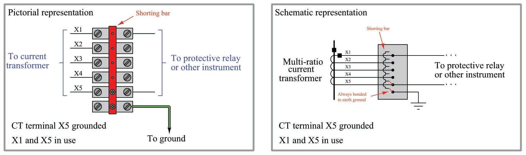
The current transformer secondary is short circuited during the operation. They are mounted using a traditional DIN mount for faster installation. CT Shorting Terminal Strips The illustration below shows the termination of a multi -ratio CT on a special shorting terminal strip.
X1 X2 X3 X4 X5. Meters relays etc is connected to the CT current transformers should always be shorted across the secondary terminals. 500 V nominal current.
Upon inspection of the main breaker wiring we found shorting jumpers on the backside of the terminal blocks for the bushing CT secondary wiring. 30 A connection method. S1 and s2 terminals to be shorted before s1-i1- and s2-i1 terminals are open circuited.
Unless a burden ie. Hello I am designing a 10MVA hydro plant. Figure 4 shows the termination of a multi- ratio CT on a shorting terminal strip.
Poles and also ample wiring space between terminals. 500 V nominal current. The reason is very high voltages will be induced at the terminals.
Answer 1 of 4. Push-in connection 1 level Rated cross section. Test disconnect terminal block nom.
The Auxiliary CT is installed as close as possible to the current transformers. Before removing a load such as a meter or relay the CT should be short circuited using a shorting block as shown in our connection diagram. 14 4 mechanical connectors provided for ease of connecting CT wires.
Shorting the secondary with primary current present allows other connections to be removed if needed. Current Transformer Shorting CTs should remain shorted during installation until secondary wiring is complete. The CT shorting blocks indicate clearly when the screw is engaged and the circuit shunted.
Product Line 3090 SCCT Current Transformer Shorting Block Environment Hardware installationmodification Resolution Warning. If you know what you are doing the voltage links and CT shorting links can be operated without having to isolate the supply. 6 mm² cross section.
Range of 5 to 13 terminal block assemblies available to meet most of your single- and three-phase application needs. It had come that way from the factory about 30 years ago. A shorting screw inserted through the shorting bar ties isolated terminal strip points together.
The terminals of the FT-1X are extended 8 to 10 inches beyond the switch blades located on the front of the switch. The relay had been religiously bench-tested every 3 years. We have available a connection diagram on a reference page on our site for your convenienceThere are many applications that require an easy.
Connect the CT polarity to one side of the terminals on the shorting block. 05 mm² - 10 mm² color. Units available in both ringless and ring type styles.
If you do then wire it just like the diagram shows with the shorting block between the CTs and the meter. Ct cabinet wiring diagram schema wiring diagram. Our new TTB range of Klippon Connect transformer terminal blocks have been designed to meet all the connection requirements of these two critical applications.
Connect the other side to Ia Ib and Ic on the meter. PHOENIX CONTACT Test disconnect terminal block - PTME 6-CT1P - 3212300. There are shorting links for the CT connections and disconnecting links for the voltage connections.
Rely on the shorting screws in the shorting terminal block to short and ground. The wiring of current and voltage transformers can be carried out particularly easily and safely with the new terminal block series even within complex circuits. 4 wire wye 4ct direct connection diagram 0 26032019 version 10 cvr i4-i4 i1-i1 i2-i2 i3-i3 vn ct shorting block detail meter normal operation ct shorted for testing or meter removal current transformer current transformer note.
Architectural wiring diagrams produce a result the approximate locations and interconnections of receptacles lighting and unshakable electrical facilities in a building. Interconnecting wire routes may be shown approximately where particular receptacles or fixtures must be upon a common circuit. I am using an SEL 387 for current differential.
The model I have linked to also has 4mm sockets for test connections to the voltages. Test disconnect terminal block nom. It will be easier to connect the wires to the terminal block if the block.
CT is a type of instrument transformer specially designed for protection and measuring purpose it will operate by the current whenever it exceeds the set value. Terminal blocks in the form of disconnect terminal blocks fuse terminal blocks and potential collective terminals are particularly effective in meeting the requirements of photovoltaic systems. Tailor-made terminal blocks up to 1500 V DC are available for all wiring tasks.
We are Professional Manufacturer of Ct Shorting Terminal Block Wiring Diagram company Factory Exporters specialize in Ct Shorting Terminal Block Wiring Diagram wiht High-Quality. An open CT secondary with primary current applied produces a hazardous voltage which. This reduces the CT burden by reducing the length of the CT secondary current conductors.
If you use a 4 terminal block In will connect to the three negative non-polarity wires and ground. Pa66 Wiring Diagram Electrical Barrier Type Terminal Block Buy Rj45 Colour Code Wiring Diagram Today Wiring Schematic Diagram Cla834 2 X Xlr Male 2 X Terminal Block 3p 3 81mm. Think of the CT as a transformer with a 1 turn primary and many tu.
Wiring between the CTs and the power monitor should include a shorting terminal block in the CT secondary circuit.
2
2
 Sliding Link Terminal Blocks Shorting Blocks
 Electrical Sensors Potential Transformers Pts And Current Transformers Cts Electric Power Measurement And Control Systems Automation Textbook
 Ct Metering Test Blocks Knowledgebase Area Pain Free Forum Electrical Help Talk Electrician Forum
2
2
2
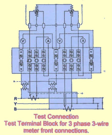 Test Terminal Blocks
 Substations Protection Systems 3 Phase Ct Circuit To The Protection Relay Lecture 04 Youtube
2
 Electrical Sensors Potential Transformers Pts And Current Transformers Cts Electric Power Measurement And Control Systems Automation Textbook
 Shorting A Ct Shorting Block Schneider Electric Support Youtube
Video How To Properly Short A Ct Shorting Block

2
 Pdf Epub Ct Shorting Block Wiring Diagram
2

No comments for "Ct Shorting Terminal Block Wiring Diagram"
Post a Comment